Friday 19 April 2019

Determination of Softening point of bitumen

Softening point of bitumen (IS 1205:1978)


Softening point of bitumen is that temperature at which it attains some degree of softness.The test is conducted by using Ring and Ball apparatus. A brass ring containing test sample of bitumen is suspended in liquid like water or glycerin at a given temperature. A steel ball is placed.upon the bitumen sample and the liquid medium is heated at a rate of 50C per minute. Temperature is noted when the softened bitumen touches the metal plate which is at a specified distance below. Generally, higher softening point indicates lower temperature susceptibility and is preferred in hot climates.

 Apparatus

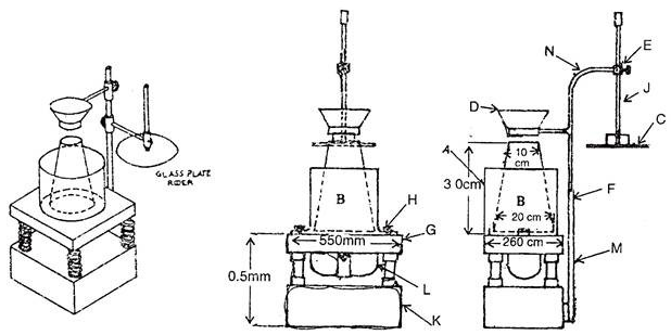
Ring and ball apparatus with all components, Thermometer, heating apparatus, Bath and stirrer.
Softening point apparatus   

Procedure

  1. Sample of bitumen is heated to a temperature between 75° and 100°C above the approximate softening point until it is completely fluid and is poured in heated rings placed on the metal plate.
  2. To avoid sticking of the bitumen to metal plate, coating is done to this with a solution of glycerin.
  3. After cooling the rings in air for 30 minutes, the excess bitumen is trimmed and rings are placed in the support.
  4. At this time the temperature of distilled water is kept at 5°C. This temperature is maintained for 15 minutes after which the balls are placed in position.
  5. Then the temperature of water is raised at uniform rate of 5°C per minute with a controlled heating unit, until the bitumen softens and touches the bottom plate by sinking of balls. At least two observations are made. For material whose softening point is above 80°C, glycerin is used for heating medium and the starting temperature is 35°C instead of 5°C.

Observations

Softening point of bitumen varying from 35 degree Celsius to 70 degree Celsius are used for various paving zones.Bitumen with higher temperature susceptibility or lower softening points are used in colder regions and vice versa.
 

Thursday 11 April 2019

Penetration test on bitumen

Penetration test on bitumen

Penetration on bitumen is conducted to classify the bitumen in different grades.This tests determine the consistency of bitumen for the purpose of grading by measuring the depth of standard needle penetrating the bitumen sample vertically under specific conditions of load, temperature time.

Apparatus

A flat bottomed cylindrical metallic dish 55mm in diameter and 35 mm in depth is required. If the penetration is of the order of 225 or more, dish of 70mm diameter and 45mm depth is required, Water bath maintained at 25 degree Celsius, Penetration apparatus: Should be such that it allows needle to penetrate without much friction & is accurately calibrated to give results in one tenth of a millimeter, Time measuring device with an accuracy of a second.

Penetrometer

Procedure

  1. Soften the material to a pouring consistency at a temperature not more than 60 degree Celsius for tars and 90 degree Celsius for bitumen above the approximate softening point and stir it thoroughly until it is homogeneous and is free from air bubbles and water.
  2. Pour the melt into the container to a depth at least 10 mm in excess of the expected penetration. Protect the sample from dust and allow it to cool in an atmosphere at a temperature between 15degree Celsius to 30 degree Celsius for one hour. Then place it along with the transfer dish in the water bath at 25 degree Celsius.
  3. Fill the transfer dish with water from the water bath to depth sufficient to cover the container completely, place the sample in it and put it upon the stand of the penetration apparatus.Clean the needle with benzene, dry it and load with the weight. The total moving load required is 100 grams, including the weight of the needle, carrier and super-imposed weights. 
  4. Adjust the needle to make contact with the surface of the sample. This may be done by placing the needlepoint in contact with its image reflected by the surface of the bituminous material.
  5. Make the pointer of the dial to read zero or note the initial dial reading.Release the needle for exactly five seconds.Adjust the penetration machine to measure the distance penetrated
  6. Make at least 3 readings at points on the surface of the sample not less than 10 mm apart and not less than l0mm from the side of the dish. After each test return the sample and transfer dish to the water bath and wash the needle clean with benzene and dry it. In case of material of penetration greater than 225, three determinations on each of the two identical test specimens using a separate needle for each determination should be made, leaving the needle in the sample on completion of each determination to avoid disturbance of the specimen.

Observations

Penetration test is generally used to determine the hardness of bitumen because of its simplicity.Softer the bitumen more will be its penetration value.For example 80/100 bitumen grade denotes the bitumen sample having penetration value between 8 mm to 10 mm.


Tuesday 12 March 2019

Conducting Soundness test on Aggregates

Soundness test on Aggregates (IS 2386 Part 5 )

Soundness of aggregates is the resistance possessed by the aggregates against the weathering agencies.To quicken this weathering action due to alternate wetting and drying and freezing thawing saturated solution of sodium sulphate or magnesium sulphate are used.

Apparatus

Sample, Weighing balance up to capacity 500 g (Least count 0.1 g), Weighing balance up to capacity 5000 g (Least count 1 g), Oven, Sieves, 80 mm, 63 mm, 40 mm, 31.5 mm, 25 mm, 20 mm, 16 mm, 12.5 mm, 10 mm, 8.0 mm, 4.75 mm, 4.0 mm, 2.36 mm, 1.18 mm, 600 micron, 300 micron, 150 micron, Chemicals Sodium sulphate or magnesium sulphate, Wire mesh bucket, Container

Sample preparation for fine aggregates

  1. Make a sieve set with sieves as per the table starting from 10 mm to 300 micron.
  2. The amount of sample to be taken for sieving is such that, it will yield not less than 100 g of each of the following sizes.
  3. Weigh 100 g of sample from each of the separated fraction and place it in separate containers for the test. 
    Sieve set for fine aggregates

 Sample preparation for coarse aggregates

  1. 1.Sieve the washed aggregates through 4.75 mm sieve and take the coarse aggregates retained over the sieve.
    2. Sieve the sample through 80,63,40,20,10,4.75  mm sieve and get the yield as per the table given below.
    3.Take the weight and put the sample in individual separate containers.
    Sieve set and Yield limits for Coarse aggregates

    Procedure

      1. Take the individual samples of aggregates and put them in solution of sodium sulphate or magnesium sulphate for about 17 hours in such a way that solution is 15 mm above the aggregates.
      2. Now dry the aggregates and puth them in oven until they obtain constant weight.
      3. Now cool down the aggregates and repeat the first step.
      4. Number of such cycles are decided by the seller and vendor agreement.
      5. After completion of these cycles the aggregates are washed from sodium sulphate solution.And this can be tested by the reaction of the wash water with barium chloride.
      6. Now dry the aggregates and put in oven till they get a constant weight.
      7. After that cool down the aggregates and sieve the fine aggregates on same sieve on which they retained before the test.
      8.  sieve the coarse aggregates on the sieves shown in table below.

      Sieves used to determine loss

       Note:-

      Average weight loss should not exceed 12 percent when tested with 10 cycles of sodium sulphate  and 18 percent  when tested with magnesium sulphate.


Thursday 7 March 2019

Determining Flakiness Index of Aggregates

  Flakiness Index of Aggregates (IS:2386 part 1)

Aggregate particles are classified as flaky when they have a thickness (smallest dimension) of less than 0.6 of their mean sieve size. The flakiness index of an aggregate sample is found by separating the flaky particles and expressing their mass as a percentage of the mass of the sample tested. This test is not applicable to aggregate passing 6.30mm sieve and retained as 63.0mm sieve. Flaky particles are considered to be unsuitable for the pavement materials. Flaky particles tends to get broken as the impact loading of vehicles passing over the road.

Apparatus

Sample,Weighing machine, Thickness gauge,Is Sieves of sizes 63mm, 50mm, 40mm, 31.5mm, 25mm, 20mm, 16mm, 10mm and 6.3mm.

Thickness Gauge


Test Procedure

  1. Take the aggregate sample having at least 200 pieces of different sized aggregates.
  2. Sieve the sample through mentioned sieves i.e., from 63mm to 6.3mm sieves.
  3. Aggregates retained on 63 mm and passing 6.3mm are discarded.
  4. Now weigh aggregate retained on different sieve and note down the total weight as “W1”
  5. The aggregate particles from each of the size range is taken and passed through corresponding gauge of thickness gauge or flakiness gauge with its thinnest side facing the slot thickness  of gauge.
  6. Each gauge length is 0.6 times the mean dimension of aggregate size range. If particle retained on 16mm and passed through 20mm size is taken, then it should pass through 10.8 mm slot of gauge which is 0.6 times the mean of 16mm and 20 mm.(i.e. [{0.6*(16+20)}/2]=10.8 mm
  7. The particles that were passing through the length gauge are weighed which is “W2”.
  8. Now calculate the flakiness index which is the ratio of weight of particles passed through thickness gauge to the total weight of the sample gauged and it is expressed in percentage.

Calculations:

Elongation index =(W2/W1) X 100

W1= Weight passed of aggregates through thickness gauge
W2= Total sample weight.
Flakiness Index should not more than 15 %  for pavement aggregates material.

Determination of Elongation Index of Aggregates

Elongation Index of Aggregates (IS:2386 part 1)

The elongation index of an aggregate is the percentage by weight of particles whose greatest dimension ( length ) is greater than 1.8 times their mean dimension.For this test aggregates passing 63 mm and retaining at 6.3 mm are taken.The elongation test is not applicable to sizes smaller than 6.3 mm. Elongated particles are considered unsuitable for the pavement. Elongated particles get broken when loaded vehicles pass over the pavement leading weakness of the structure.These particles also create problem in close packing of the aggregates leading to voids in concrete.

Apparatus

Sample,Weighing machine, Length gauge,Is Sieves of sizes 63mm, 50mm, 40mm, 31.5mm, 25mm, 20mm, 16mm, 10mm and 6.3mm.
Length Gauge

Test Procedure

  1. Take the aggregate sample having at least 200 pieces of different sized aggregates.
  2. Sieve the sample through mentioned sieves i.e., from 63mm to 6.3mm sieves.
  3. Aggregates retained on 63 mm and passing 6.3mm are discarded.
  4. Now weigh aggregate retained on different sieve and note down the total weight as “W1”
  5. The aggregate particles from each of the size range is taken and passed through corresponding gauge of length gauge or elongation gauge with its longest side facing the width of gauge.
  6. Each gauge length is 1.8 times the mean dimension of aggregate size range. If particle retained on 16mm and passed through 20mm size is taken, then it should pass through 32.4mm length gauge which is 1.8 times the mean of 16mm and 20 mm.(i.e. [{1.8*(16+20)}/2]=32.4 mm
  7. The particles that were retained on the length gauge are weighed which is “W2”.
  8. Now calculate the elongation index which is the ratio of weight of particle retained on length gauge to the total weight of the sample gauged and it is expressed in percentage.

Calculations:

Elongation index =(W2/W1) X 100

W1= Weight retained of aggregates on length gauge
W2= Total sample weight.
Elongation Index should not more than 15 %  for pavement aggregates material.

Sunday 3 March 2019

Specific gravity of fine aggregate (sand) is defined as the ratio of the weight of given volume of aggregates to the weight of equal volume of water at the same temperature.The specific gravity of sands is considered to be around 2.7.

Apparatus

A weighing balance of capacity of about  kg with least count of 0.5 g., an oven with range up to 110ÂșC,Pycnometer of about 1 litre capacity and 6mm hole at the top, tray, funnel and filter paper etc.
 

Pycnometer Apparatus


Procedure of Test

  1. Take about 500g of clean sample of fine aggregates and pour it into the pycnometer.
  2. Fill it with distilled water up to brim.Also remove the entrapped air from the container.
  3. Clean the outer surface of pycnometer with a clean cloth and weigh it (W1)
  4. Empty the pycnometer completely and fill it again with water up to same level and weight it (W2)
  5. Drain water from the fine aggregate sample through a filter paper and air dry it.
  6. Place the sample inside oven for 24 hours with range of temperature  to 110ÂșC
  7. Cool down the sample and weigh it (W3)

Calculations

Apparent specific gravity = (Weight of dry sample/Weight of equal volume of water )
= W3/(W1-W2)

Saturday 2 March 2019

Calculating the Bulk, apparent Specific gravity and water absorption in coarse aggregates


 Specific Gravity of Coarse Aggregates

It is defined as the ratio of the mass of the solid in given volume of sample to the mass of the equal volume of water at same temperature.It generally varies from 2.6 to 2.9 range. Specific gravity of aggregates generally defines the strength of aggregates . Stones of low specific gravity are generally considered to be weak. The specific gravity helps for choosing right stone for pavement and concrete mixes.It is also useful for the weight volume conversion and calculating the void content in aggregates.In case of Apparent Specific Gravity the volume measurement only includes the volume of the aggregate particle; it does not include the volume of any water permeable voids. The mass measurement only includes the aggregate particle. Apparent specific gravity is intended to only measure the specific gravity of the solid volume, therefore it will be the highest of the aggregate specific gravities. It is formally defined as the ratio of the mass of a unit volume of the impermeable portion of aggregate (does not include the permeable pores in aggregate) to the mass of an equal volume of gas-free distilled water at the stated temperature.In case of Bulk Specific Gravity The volume measurement includes the overall volume of the aggregate particle as well as the volume of the water permeable voids. The mass measurement only includes the aggregate particle. Since it includes the water permeable void volume, bulk specific gravity will be less than apparent specific gravity. It is formally defined as the ratio of the mass of a unit volume of aggregate, including the water permeable voids, at a stated temperature to the mass of an equal volume of gas-free distilled water at the stated temperature.

Apparatus

Weighing machine up to 3 kg capacity, wire basket having mesh size not more than 6.3 mm,oven, container up to 5 liter capacity, soft cloth , tray etc.
Specific gravity apparatus frame setup with wire mesh bucket

Procedure


  1. Take about 2 kg of sample and sieve it from 10 mm sieve to remove fines. Now immerse the sample with wire bucket in a water filled container.
  2. Immediately after immersion the entrapped air is removed from the sample by lifting the basket containing it 25 mm above the base of the tank and allowing it to drop at the rate of about one drop per second. The basket and aggregate should remain completely immersed in water for a period of 24 hour afterwards at temperature of 22° – 32°C. 
  3.  Now the water is drained out and The basket and  the sample are weighed while suspended in water at a temperature of 22° – 32°C. The weight while suspended in water is noted W1g. 
  4. Basket and aggregates are removed from water and allowed to drain for a few minutes after which the aggregates are transferred to the dry absorbent clothes. The empty basket is then returned to the tank of water dipped 25 times and weighed in water W2 g.
  5. Aggregates placed on the absorbent clothes are surface dried till no further moisture could be removed by this cloth. Then aggregates are dried for at least 10 minutes until the aggregates are completely surface dry. The surface dried aggregate is then weighed  W3 g.
  6. The aggregate is placed in a shallow tray and kept in an oven maintained at a temperature of 110° C for 24 hrs. It is then removed from the oven, cooled in an air tight container and weighted=W4


Observations and Calculations

Weight of saturated aggregate suspended in water with basket = W1 g.
Weight of basket suspended in water = W2 g.
Weight of saturated surface dry aggregate in air = W3 g.
Weight of oven dry aggregate = W4 g.
Weight of saturated aggregate in water = W1 – W2 g
Weight of water equal to the volume of the aggregate = W3–( W1W2)g

Bulk Specific gravity = W3 / (W3– (W1W2))
Apparent specific gravity = W4/ (W4– (W1W2))
 Water Absorption = ((W3 W4) / W4) x 100

Friday 1 March 2019

Los Angeles Abrasion Test

                       Los Angeles Abrasion Test for Aggregate

Abrasion test is carried out to test the hardness property of aggregates and to decide whether they are suitable for the pavement or not.The principle of Los Angeles abrasion test is to find the percentage wear due to relative rubbing action between the aggregate and steel balls used as per code IS:2386 (Part IV)-1963.

Apparatus

The test sample consists of clean aggregates dried in oven at 105° – 110°C,  Los Angeles Machine, Abrasive charge: Cast iron or steel balls, approximately 48mm in diameter and each weighing between 390 to 445 six to twelve balls are required, Balance of capacity 5 kg or 10 kg, Sieve: 1.70, 2.36, 4.75, 6.3, 10, 12.5, 20, 25, 40, 50, 63, 80 mm IS Sieves. Drying oven,tray.


Procedure

  1.  Select the grading to be used in the test such that it conforms to the grading to be used in construction, to the maximum extent possible.Take 5 kg of sample for grading A, B, C & D and 10 kg for grading E, F & G as shown in Table . Table : Number of Spheres as per Gradation of Aggregate.
  2.  Choose the abrasive charge as per Table  depending on grading of aggregates. 
  3.  Place the aggregates (weighed W1) and abrasive charge on the cylinder and fix the cover. 
  4.  Rotate the machine at a speed of 30 to 33 revolutions per minute. The number of revolutions is 500 for grading A, B, C & D and 1000 for gradings E, F & G. 
  5.  The machine is stopped after the desired number of revolutions and material is discharged to a tray.
  6. The entire stone dust is sieved on 1.70 mm IS sieve. 8. The material coarser than 1.7mm size is weighed (W2) correct to one gram. 
Image result for los angeles abrasion test pdf

Gradation vs number of spheres of abrasive charge


Calculation:

Original weight of aggregate sample = W1 g
Weight of aggregate sample retained = W2 g 
Weight passing 1.7mm IS sieve = W1 – W2 g
 Abrasion Value = (W1 – W2 ) / W1 X 100

Abrasion Value and Suitability for types of pavement

Thursday 28 February 2019

Aggregates Impact Value Test

Aggregates Impact Value Test (IS 2386 Part 4)

• Toughness is the property of a material to resist the impact. Due to traffic loads, the road stones are subjected to the pounding action or impact and there is possibility of stones breaking into smaller pieces. The road stones should therefore be tough enough to resist fracture under impact. A test designed to evaluate the toughness of stones i.e., the resistance of the stones to fracture under repeated impacts may be called an impact test for road stones.

Apparatus

 Impact testing machine: The machine consists of a metal base with a plane lower surface supported well on a firm floor, A cylindrical metal measure of 75mm dia. and 50mm depth,  tamping rod of 10mm circular cross section and 230mm length, rounded at one end, Sieves of sizes - 12.5mm, 10mm and 2.36mm, Oven: A thermostatically controlled drying oven capable of maintaining constant temperature between 100° c and 110°c.

Aggregate impact testing machine Theory: Aggregate impact value gives a relative measure of the resistance of an aggregate to sudden shock or impact, which in some aggregates differs from its resistance to a slow compressive load. Aggregate impact value shall be less than 45% for aggregate used in concrete for concrete other than wearing surface and 30% for concrete used in wearing surface.  
Impact Testing Machine

Sampling

  1. Take aggregates passing through 12.5mm IS Sieve 100% • Retention on 10mm IS Sieve 100% 
  2. The sample should be oven-dried for 4hrs. at a temperature of 100 to 110oC and cooled.
  3. The measure should be about one-third full with the prepared aggregates and tamped with 25 strokes of the tamping rod.

Procedure

  1. • The cup of the impact testing machine should be fixed firmly in position on the base of the machine.
  2. Whole of the test sample is to be placed in it and compacted by 25 strokes of the tamping rod.
  3. Weigh the sample with cup to nearest gram.Let it be W1. Also weigh the empty cup, let it be W2.
  4.  The hammer should be raised to 380mm above the upper surface of the aggregates in the cup and allowed to fall freely onto the aggregates.
  5. The test sample should be subjected to a total of 15 such blows, each being delivered at an interval of not less than one second.
  6. Lock thee hammer at the top and remove the cup from the base of the machine.
  7. Sieve the crushed sample through the sieve of 2.36 mm. Weigh this fraction and say it is W3

 Calculation 


 Aggregate impact value = W3/(W1-W2) x100

W1=Weight of sample with cylinder
W2=Weight of cylinder
W3= Weight of fraction passing through 2.36 mm sieve.


Impact value vs Strength


Wednesday 27 February 2019

Vee Bee Consistometer Test for Workability of concrete

Vee Bee Consistometer Test

 It is based on measuring the time (Called VEE BEE time) needed to change the shape of a concrete mix from a frustum cone to a cylinder (these shapes are standardized by the apparatus of this test), by vibrating and compacting the mix. The more VEE BEE time needed the less workable the mix is. This method is mostly useful for measuring workability of stiff mixes.

 Apparatus

  Cylindrical container with diameter = 240 mm, and height = 200 mm
Mold: the same mold used in the slump test.
Disc : A transparent horizontal disc attached to a rod which slides vertically
Vibrating Table : 380x260 mm, supported by four rubber shock absorbers
Tamping Rod ,Stop watch  for measuringVee Bee Time.

Vee Bee Consistometer

  Procedure

  1.  Place the slump cone inside the sheet metal cylindrical pot of the consistometer. Pour the concrete inside the cone and tamp it properly.
  2. The glass disc attached to the swivel arm is turned and placed on the top of the concrete in the pot.
  3. The electrical vibrator is then switched on and simultaneously a stopwatch started.
  4. The vibration is continued till such time as the conical shape of the concrete changes in to the  cylindrical shape.
  5. This can be judged by observing the glass disc from the top disappearance of transparency. 
  6. Immediately when the concrete fully assume a cylindrical shape, the stopwatch is switched off.
  7. The time required for the shape of concrete to change from slump cone shape to cylindrical shape in second is known as Vee Bee time.
  8. This method is very suitable for very dry concrete whose slump value cannot be measure by slump test.

  Note

The test fails if Vee Bee Time is less than 5 seconds.For this flow test may be used.


Workability vs Vee Bee time

Flow test for the workability of concrete

 Flow Test for Concrete (IS1159:1959)

The flow table test or flow test is a method to determine the consistence of fresh concrete.This test is giving us the ability of concrete to flow under the gravitational force when poured and compacted  within the cone and suddenly lifted up.

Equipment

Flow table with a grip and a hinge, 70 cm x 70 cm,  Abrams cone, open at the top and at the bottom -  Water,Tamping rod of 16mm diameter, Scale for measurement.


Image result for flow test

Flow table apparatus


Procedure

  1.  The flow table is wetted properly with water.
  2. The cone is placed on the flow table at the center and filled with freshly prepared concrete in two layers, each layer is given 25 blows with tamping rod.
  3. After waiting for 30 seconds the cone is lifted all at once, allowing the concrete to flow freely.
  4.  The flow table is then lifted up up to 12.5 mm and then dropped 15 times within 30 seconds, causing the concrete flow a little bit further. 
  5. After this the diameter of the concrete is measured in c.m. in a 6 evenly distributed directions and take the average of these measurements.

Calculations 

https://i0.wp.com/civilblog.org/wp-content/uploads/2013/05/concrete-flow-table-1.jpg?ssl=1  

Flow percentage and Consistency of concrete

Tuesday 26 February 2019

Compaction Factor Test for the Workability of Concrete


                  Compaction Factor Test

 Compaction factor test is used to check the workability of concrete in laboratory. The compaction factor may be defined as the ratio of weights of partially compacted concrete to the fully compacted concrete.Its value ranges from 0.8- 0.92. Compaction factor test is used for concretes of lower workability (slump<50mm). It is governed by Is Code 1199:1999.

Apparatus


Compaction factor test Apparatus, scoop, trowel, weighing balance.
The compaction factor test apparatus: basic dimensions

Compaction factor test apparatus


 Sampling


 Concrete sample prepared in laboratory as per design mix or prepared in red mix plant.

Procedure


1.   Apply Grease on the inner surface of the apparatus.

2.   Measure the mass as W1 kg by weighing the cylinder accurately and fix the cylinder on the base in such a way that the central points of hoppers and cylinder lie on one vertical line.

3.   Fill the freshly mixed concrete in upper hopper part. Then release the trap door so that the concrete to fall into the lower hopper.

4.   Fall of the concrete into the lower hopper causes standard Compaction immediately.

5.   After the concrete has come to rest, open the trap door of lower hopper and let concrete to fall in to cylinder.

6.   Remove the excess concrete above the top of the cylinder. Clean the cylinder from all sides properly

7.   Weight the partially compacted concrete filled in the cylinder along with it and say it W2 kg.

8.    Refill the cylinder with the same sample of concrete in 3 layers, by tamping each layer 25 times as to expel all the air and  to obtain full compaction of the Concrete.

9.    Struck off level the concrete and weigh cylinder filled with fully compacted concrete. Let the mass be W3 kg.

10.  Calculate the compaction factor as following


Calculation

Compaction factor = (W2-W1)/(W3-W1)

W1=Weight of empty cylinder
W2= Weight of partially compacted concrete with cylinder
W3=Weight of fully compacted concrete with cylinder

Compaction factor and application of concrete